By: Team AY1920S1-CS2103T-T13-2 Since: Sep 2019 Licence: MIT
- 1. Introduction
- 2. Setting up
- 3. Design
- 4. Implementation
- 5. Documentation
- 6. Testing
- 7. Dev Ops
- Appendix A: Product Scope
- Appendix B: User Stories
- Appendix C: Use Cases
- Appendix D: Non Functional Requirements
- Appendix E: Glossary
- Appendix F: Instructions for Manual Testing
1. Introduction
Mortago is a mortuary management system for hospitals. This developer guide serves as a documentation of the interactions with Mortago. As a developer, you will be able to gain a better understanding of how Mortago works.
This developer guide is organised in a top-down approach, starting with Architecture Design. You may jump to any section by clicking on the heading in the contents page.
2. Setting up
Refer to the guide here.
3. Design
3.1. Architecture
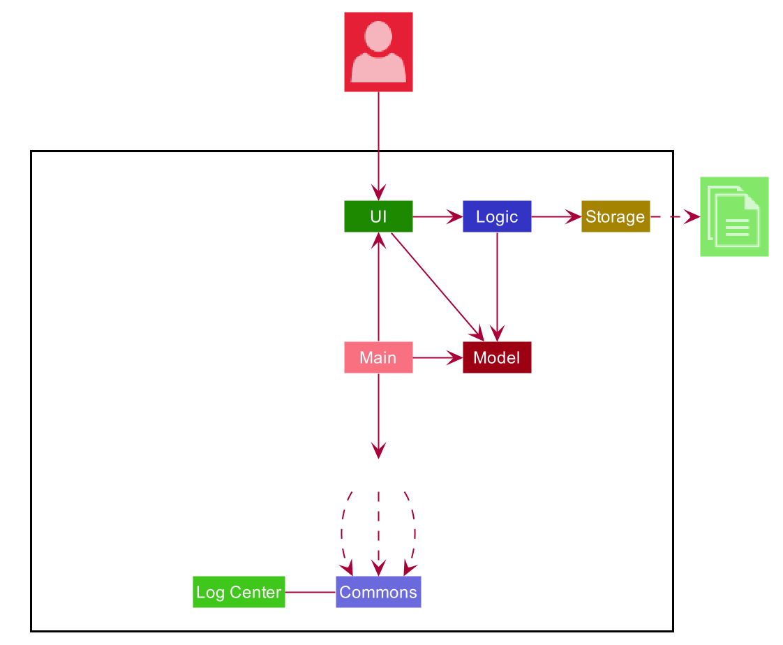
The Architecture Diagram given above explains the high-level design of the App. Given below is a quick overview of each component.
The .puml files used to create diagrams in this document can be found in the diagrams folder.
Refer to the Using PlantUML guide to learn how to create and edit diagrams.
|
-
At app launch: Initializes the components in the correct sequence, and connects them up with each other.
-
At shut down: Shuts down the components and invokes cleanup method where necessary.
Commons represents a collection of classes used by multiple other components.
The following class plays an important role at the architecture level:
-
LogsCenter: Used by many classes to write log messages to the App’s log file.
The rest of the App consists of four components.
Each of the four components
-
Defines its API in an
interfacewith the same name as the Component. -
Exposes its functionality using a
{Component Name}Managerclass.
For example, the Logic component (see the class diagram given below) defines it’s API in the Logic.java interface and exposes its functionality using the LogicManager.java class.
How the architecture components interact with each other
The Sequence Diagram below shows how the components interact with each other for the scenario where the user issues the command delete -b 1.
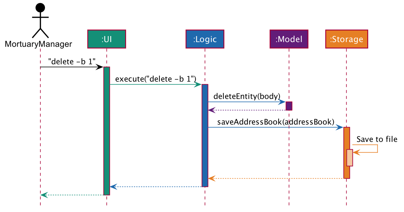
delete -b 1 commandThe sections below give more details of each component.
3.2. UI Component
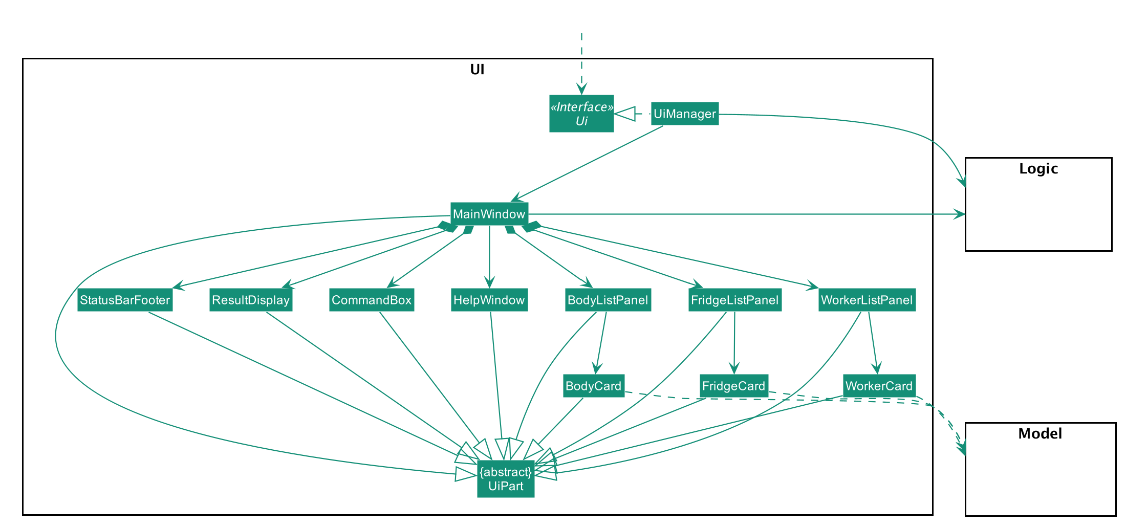
API : Ui.java
The UI consists of a MainWindow that is made up of parts e.g.CommandBox, ResultDisplay, BodyListPanel, WorkerListPanel, FridgeListPanel, StatusBarFooter etc. All these, including the MainWindow, inherit from the abstract UiPart class.
The UI component uses JavaFx UI framework. The layout of these UI parts are defined in matching .fxml files that are in the src/main/resources/view folder. For example, the layout of the MainWindow is specified in MainWindow.fxml
The UI component,
-
Executes user commands using the
Logiccomponent. -
Listens for changes to
Modeldata so that the UI can be updated with the modified data.
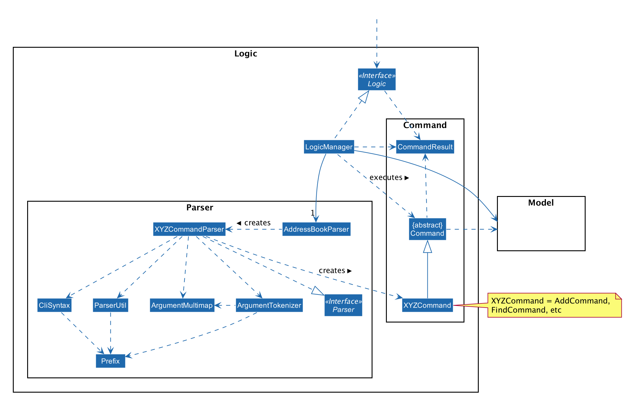
3.3. Logic Component
API :
Logic.java
-
Logicuses theAddressBookParserclass to parse the user command. -
This results in a
Commandobject which is executed by theLogicManager. -
The command execution can affect the
Model(e.g. adding a body). -
The result of the command execution is encapsulated as a
CommandResultobject which is passed back to theUi. -
In addition, the
CommandResultobject can also instruct theUito perform certain actions, such as displaying help to the user.
Given below is the Sequence Diagram for interactions within the Logic component for the execute("delete -b 1") API call.
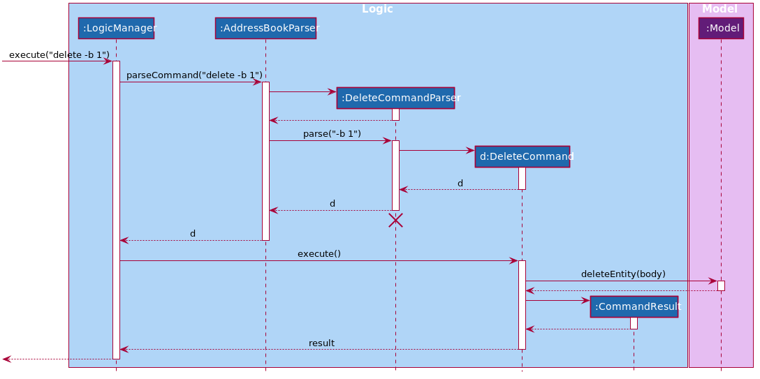
delete -b 1 Command
The lifeline for DeleteCommandParser should end at the destroy marker (X) but due to a limitation of PlantUML, the lifeline reaches the end of diagram.
|
3.4. Model Component
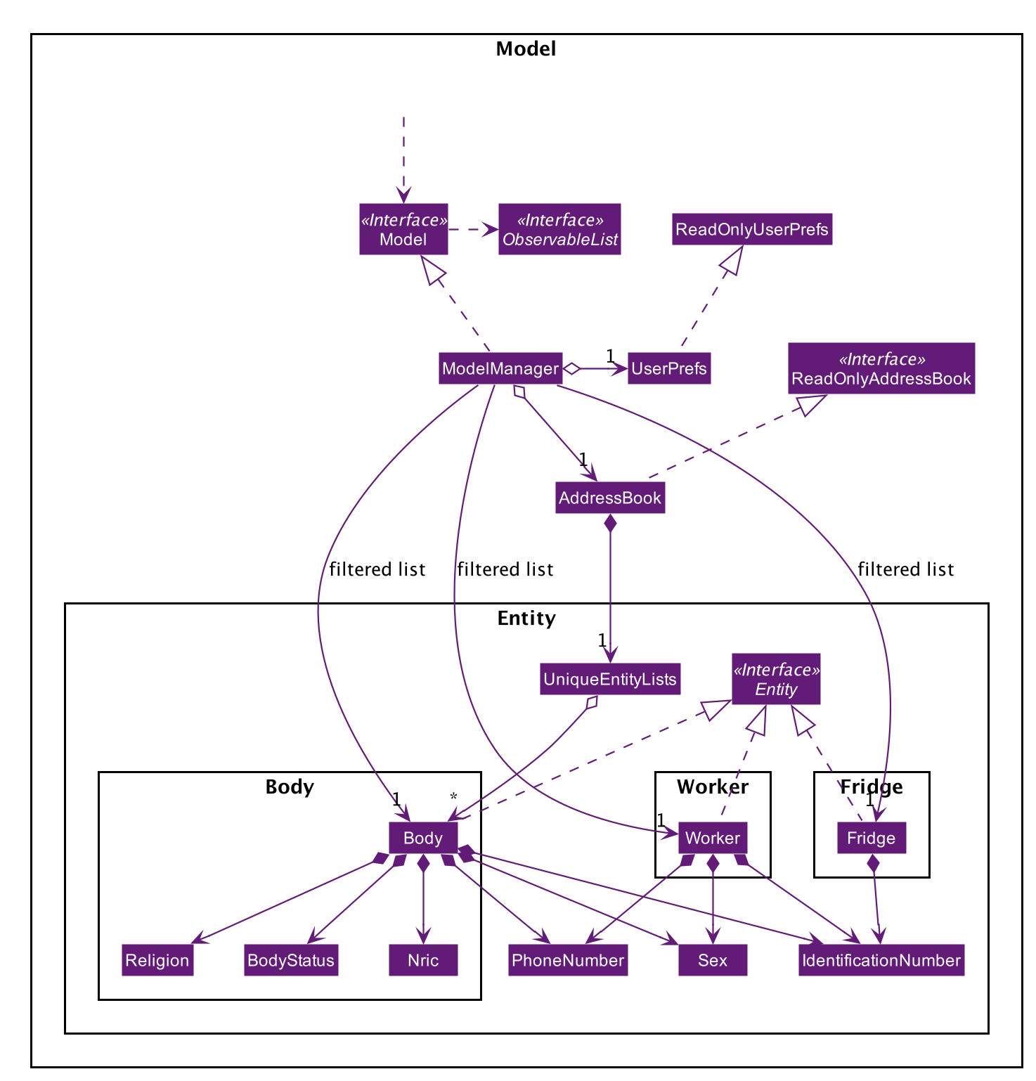
API : Model.java
The Model,
-
stores a
UserPrefobject that represents the user’s preferences. -
stores the Address Book data.
-
exposes an unmodifiable
ObservableList<Body>that can be 'observed' e.g. the UI can be bound to this list so that the UI automatically updates when the data in the list change. -
does not depend on any of the other three components.
3.5. Storage Component
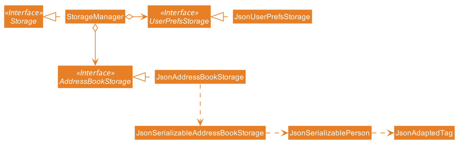
API : Storage.java
The Storage component,
-
can save
UserPrefobjects in json format and read it back. -
can save Mortago data in json format and read it back.
3.6. Common Classes
Classes used by multiple components are in the seedu.addressbook.commons package.
4. Implementation
This section describes some noteworthy details on how certain features are implemented.
4.1. Unique Identification Number
In Mortago, you will find that each entity is assigned a unique IdentificationNumber.
-
The
IdentificationNumberfor each entity is a central aspect of Mortago as most interactions with and references of entities in the application are made through theirIdentificationNumbers. -
You can identify different entities solely based on their
IdentificationNumberdue to its uniqueness, without relying on attributes such asnamewhich may have similar duplications within the system. -
IdentificationNumbersin Mortago consist of two parts:String typeOfEntitythat tells you whether it is a worker, body or fridge, andInteger idNumthat refers to its unique ID number. -
Each
IdentificationNumberis automatically generated within the application, based on the next sequential ID number available.
4.1.1. Implementation
The generation of unique IdentificationNumbers is facilitated by UniqueIdentificationNumberMaps. UniqueIdentificationNumberMaps keeps three HashMap, one for each entity.
In each HashMap, the Integer ID number serves as the key, which maps to the entity it is assigned to. This keeps track of the numbers currently assigned to all entities and allows the next free Integer to be assigned to a newly added entity.
The code snippet below demonstrates how the next free number is determined.
    private static Integer putWorker(Worker worker) {
        Set<Integer> keys = uniqueWorkerMap.keySet();
        int numOfKeys = keys.size();
        for (int id = 1; id <= numOfKeys; id++) {
            if (uniqueWorkerMap.get(id) == null) {
                uniqueWorkerMap.put(id, worker);
                return id;
            }
        }
        int newId = numOfKeys + 1;
        uniqueWorkerMap.put(newId, worker);
        return newId;
    }
In the above putWorker method, the set of keys representing the existing ID numbers are generated and iterated through, based on the size of the keySet.
This sequential iteration checks for any number that is not assigned to any worker (i.e. gap) due to a prior deletion of its assigned worker, which removes the mapping of the ID number to the deleted worker.
If there is an existing gap in the sequential iteration of numbers, this number is assigned to the newly added worker.
If there is no gap available, the next highest number is assigned to the worker.
This leads us to forumulate the execution sequence of generating a unique IdentificationNumber for a worker:
-
The user executes
add -w /name Zach …to add a new worker to Mortago. -
AddCommandParserparses the given input and calls theWorkerconstructor. -
In the constructor, the worker’s
IdentificationNumberis created usingIdentificationNumber::generateNewWorkerId(). -
Consequently,
generateNewWorkerId()creates a newIdentificationNumber, where the number is determined after the execution ofUniqueIdentificationNumberMaps::addEntity(). -
UniqueIdentificationNumberMaps::addEntity()subsequently callsUniqueIdentificationNumberMaps::putWorker(), which inserts the worker into the workerHashMapand returns an ID number that is currently not assigned to a worker.
The figure below illustrates the sequence diagram of the aforementioned steps.
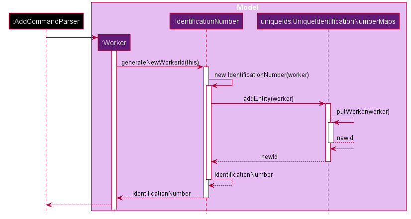
IdentificationNumber Sequence DiagramYou will find that the execution sequence will be similar for the generation of unique IdentificationNumber for fridges and bodies.
4.1.2. Design Considerations
When designing this feature, it is important to keep in mind the scalability of the application. When the number of entities grows exponentially, the ID number can become arbitrarily large if gaps in the middle are not (re)assigned.
Aspect: Tracking of numbers and determination of next free number*
-
Alternative 1: Three counters that track the total number of each entity in the system and assigns the next highest number to the added entity.
-
Pros:
-
Easy to implement.
-
-
Cons:
-
Does not cater for deletion of entity as deletion creates a gap which will be left unfilled.
-
-
-
Alternative 2 (current choice): A
HashMapkeeping track of the ID numbers and their respective assigned entity.-
Pros:
-
HashMapallows itskeySetto contain unique ID numbers. -
HashMapcaters for deletion of entities as thekeySetcan be iterated through to check for any gaps introduced during deletion. -
HashMapalso allows the assigned (mapped) entity to be made accessible via the O(1)HashMap#get()method.
-
-
Cons:
-
Harder to implement, especially for unit testing since a unique
IdentificationNumbercannot be duplicated usually.
-
-
Alternative 2 is chosen due to the comprehensive benefits of utilizing HashMap given below:
-
Tracking of unique keys
-
Catering for deletion of ID numbers and filling of the gap
-
Increasing the ease of accessibility of mapped entities
The difficulty in testing can be circumvented by executing UniqueIdentificationNumberMaps::clearAllEntries()
before each unit test. This resets the HashMaps and allows the newly added entities to start with the first ID number, simulating a fresh launch of the application.
4.2. Photo Feature
When adding a worker in Mortago, you can assign a photo to the worker so as to identify your workers. This is especially useful when you are more visual oriented as this allows you to identify your workers more easily when sieving through a long list of workers.
4.2.1. Implementation
This section covers how the Photo feature is implemented. To gain a better overview of its implementation, you can refer to the following class diagram that illustrates how Photo and Worker are associated with the Ui component.
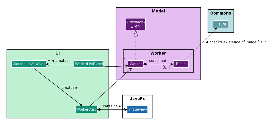
Here, notice that a WorkerCard contains an ImageView which serves to display the Photo. The ImageView displays the Photo by first retrieving the file path of the photo through the Worker in WorkerCard. This is demonstrated in the following code snippet:
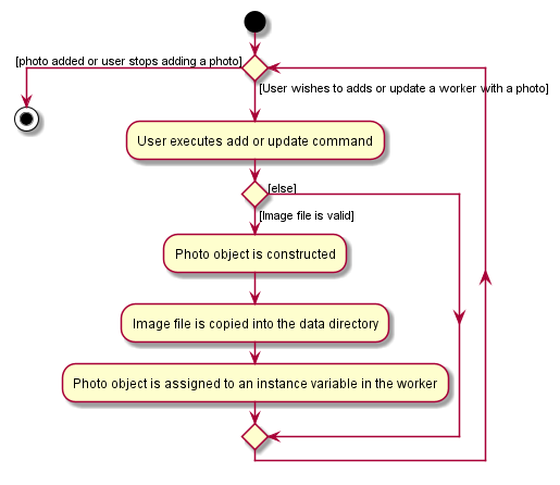
displayPhoto.setImage(new Image(worker.getPhoto().get().getPathToDataDirectory()));This brings us to explain how Photo is constructed, as demonstrated in the following diagram and the sequence of steps further below.
-
When the user wishes to add a photo, the user can do this through the add or update command.
-
Before constructing a
Photoobject, the validity of the absolute file path of the image is checked first through thePhoto::isValidPhoto(pathToPhoto)method, as part of a defensive programming measure.This method checks whether the image file exists, using FileUtil::isFileExists(Path)as seen in the class diagram above, and whether it ends with the common image file extensions:.jpeg,.jpgand.png. -
If the file is valid, the
Photoobject is constructed. -
In its construction, the image file is copied into the
data/images/directory (where all images are stored) and this path is saved as an instance variable,dataDirectory. ThePhotois then assigned to an instance variable inWorker.Copying the image file allows the application to retrieve it even when the user has deleted the original file.
After construction of the Photo, when the image needs to be retrieved, Photo#getPathToDataDirectory needs to be called to obtain the modified file path to the image, which can then be used for display via the ImageView node. The following code snippet shows how the file path is modified so that it can be used directly for image retrieval and display.
    /**
     * Returns the file path of the copied photo in the data directory.
     * Intended for {@code ImageView} to reference to the photo.
     */
    public String getPathToDataDirectory() {
        return "file://" + Paths.get(dataDirectory).toAbsolutePath().toUri().getPath();
    }
Note that appending file:// to the front is necessary for file retrieval.
4.2.2. Design Considerations
When designing Photo, it is important to consider the user profile. Given that our users are generally fast at typing and prefers a Command Line Interface, some thoughts had to be made to design how the user can upload the photo.
Aspect: How the user uploads the photo
-
Alternative 1 (current choice): Users must specify the absolute file path of the image file
-
Pros: This ensures accurate retrieval of the file.
-
Cons: Users require additional steps to obtain the absolute file path of the file.
-
-
Alternative 2 (current choice): Users can upload their image file through a popup dialog
-
Pros: Graphical dialog allows visual navigation towards where the file is.
-
Cons: Users might find it slow to navigate through a graphical interface.
-
Alternative 1 is chosen due to the user profile of our application. As they prefer typing over using the mouse, it will be much faster for them to provide the absolute file path as compared to navigating through a graphical dialog.
4.3. Undo/Redo Feature
The undo/redo feature allows you to undo a command that you have made or redo a command you have undone.
4.3.1. Implementation
You can find the core of undo/redo in the undo/redo history of ModelManager.
The history stores UndoableCommands, and an UndoCommand or RedoCommand will undo() or redo() commands in the history.
The design of UndoableCommand uses the Command pattern, a common design pattern often used in software engineering.
It allows each individual command to be undone/redone at a high-level without needing the specific command type to be known.
Classes related to undo/redo and their relationships are shown in Figure 12.
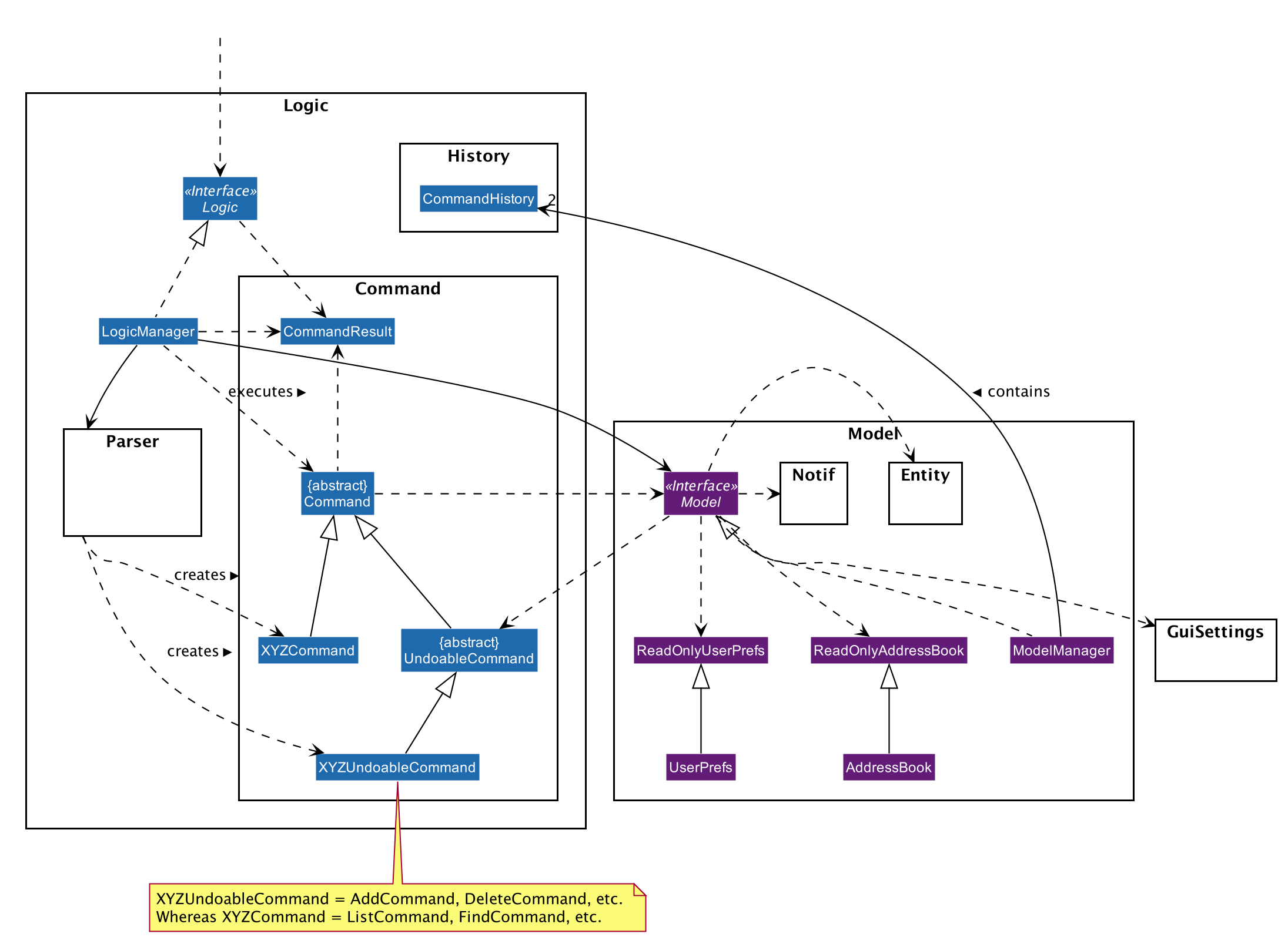
Architecture
To start off, you will find two instances of CommandHistory in ModelManager. They are stored internally as commandHistory and undoHistory.
commandHistory stores previously executed commands while undoHistory stores previously undone commands.
CommandHistory wraps a Deque<UndoableCommand>. Its methods imposes a MAX_SIZE which determines how many commands can be stored in the command history.
In ModelManager, four key operations to access and modify CommandHistory are implemented:
-
ModelManager#addExecutedCommand(UndoableCommand command)— Adds a command that was executed to the start ofcommandHistory. -
ModelManager#getExecutedCommand()— Removes the last command that was executed and added tocommandHistoryand returns it. -
ModelManager#addUndoneCommand(UndoableCommand command)— Adds a command that was undone to the start ofundoHistory. -
ModelManager#getUndoneCommand()— Removes the last command that was undone and added toundoHistoryand returns it.
In the Model interface implemented by ModelManager, these four operations are respectively exposed as
Model#addExecutedCommand(UndoableCommand command), Model#getExecutedCommand(), Model#addUndoneCommand(UndoableCommand command), and Model#getUndoneCommand().
Next, the UndoableCommand stored in the Model is actually a normal Command that changes program state.
The UndoableCommand class is an abstract class that extends the abstract Command class, as shown in Figure 12. Commands like AddCommand or UpdateCommand extends UndoableCommand instead of Command.
Commands that don’t change the user-visible program state, like FindCommand, can still inherit directly from Command.
Here is where the Command pattern comes in. A class extending UndoableCommand must implement an additional method, UndoableCommand#undo(Model model). This means that every child class of UndoableCommand has a custom undo implementation.
UndoableCommand#redo(Model model) is a concrete implementation of the redo mechanism and is inherited by all child classes.
Lastly, undo/redo is initiated when user input creates an UndoCommand or RedoCommand. When either of them are executed, they respectively get the last
executed or undone command from the CommandHistory in ModelManager. As the retrieved command is an instance of UndoableCommand, an attempt will be made to execute UndoableCommand#undo(Model model) or UndoableCommand#redo(Model model).
If it is successful, undo/redo is succesful. Otherwise, an error message is shown.
This is the mechanism of undo/redo, from start to end.
The sequence diagram below shows how an undo command works to undo a ClearCommand:
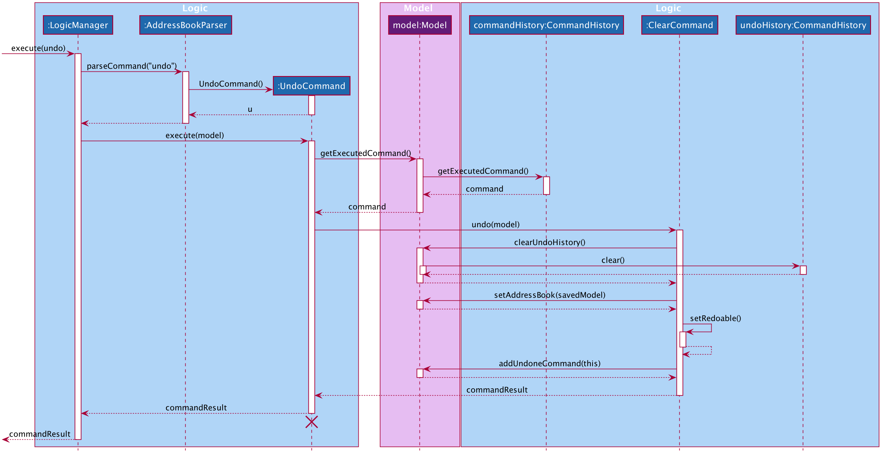
The lifeline for UndoCommand should end at the destroy marker (X) but due to a limitation of PlantUML, the lifeline reaches the end of diagram.
|
If a redo command was executed afterwards, the ClearCommand would simply be executed again.
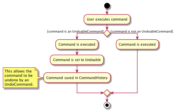
The following activity diagram shows what happens when a user executes a new UndoableCommand. In this case, it is the ClearCommand being undone. The control flow is similar for other UndoableCommands; they only differ in the implementation of undo().
Defensive programming
To defend against improper undoing or redoing, an UndoableCommand can only be added to the commandHistory or undoHistory of ModelManager through its execute() or undo() method.
Additionally, UndoableCommand contains a small inner class, the enumeration UndoableCommandState which allows an UndoableCommand to have its state set to any value in the enumeration.
The values are as shown below.
    /**
    * Enumerates through the possible states of an UndoableCommand.
    */
    public enum UndoableCommandState {
        UNDOABLE, REDOABLE, PRE_EXECUTION
    }
Before a command is undone or redone, the command’s state is checked for validity. An example is shown below in the redo() method.
    /**
     * Re-executes an UndoableCommand if it had been previously undone.
     */
    public CommandResult redo(Model model) throws CommandException {
        if (getCommandState() != UndoableCommandState.REDOABLE) {
            return new CommandResult(MESSAGE_NOT_UNDONE_BEFORE);
        }
        return execute(model);
    }
As shown in the code snippet, when an UndoableCommand is redone, the method first checks that its state was set to UNDOABLE.
These states are only changed when a Command#execute(Model model) or UndoableCommand#undo(Model model) has successfully executed.
Therefore, it is unlikely that an UndoableCommand will be unwittingly undone or redone in error.
4.3.2. Design considerations
When designing the undo/redo feature, scalability and speed were the key considerations. There was also an extra layer of difficulty as Mortago has automated commands that are both time-based and user-triggered. After the analysis described below, the Command pattern was thought to be the best solution.
Aspect: Designing the undo/redo mechanism
Alternative 1 was chosen despite its difficult implementation because it is faster and more scalable.
-
Alternative 1: Individual command knows how to undo/redo by itself.
-
Pros:
-
Better scalability. Will use less memory (e.g. For
add, only the added entity needs to be saved). -
Faster for big programs.
-
Easier to implement defensive measures.
-
-
Cons:
-
Must implement custom undo functions for each command.
-
More difficult to implement and maintain.
-
-
-
Alternative 2: Saves the whole program state.
-
Pros:
-
Easy to implement and maintain.
-
-
Cons:
-
Likely to use a lot of memory.
-
Slower for big programs.
-
-
Aspect: Handling automated timed commands
Mortago has a Notification feature, which are user-triggered automated commands that are triggered by time. Though the undo/redo feature does not support it directly, the Notification can make changes to program state at any time. When undoing or redoing, it was essential that data integrity was preserved.
Alternative 1 was chosen as it causes almost no overhead, guarantees data integrity, and causes the user the least inconvenience.
-
Alternative 1: Allow automated commands to be undone
-
Pros:
-
Causes minimal overhead as only one additional command needs to be stored.
-
Maintains data integrity.
-
Allows the user to undo automated changes, if it is not desired.
-
Shows consistency and will not cause visual jumps between states.
-
-
Cons:
-
Confuses the user initially.
-
-
-
Alternative 2: Do not undo the automated command
-
Pros:
-
Easiest to implement.
-
-
Cons:
-
Confuses the user initially.
-
Causes visible jumps between states (e.g. The user might see changes to 2 fields being undone even though his
updatecommand only changed one field). -
Loss of data integrity.
-
-
Aspect: Storing executed/undone commands
-
Alternative 1 (current choice): Store
UndoableCommand(s) only.-
Pros:
-
Logic can be reused for both executed and undone commands.
-
Easy to implement.
-
Uses less space.
-
-
Cons:
-
Loses some information about
Commandsthat were previously executed.
-
-
-
Alternative 2: Store all
Commands.-
Pros:
-
No loss of information.
-
-
Cons:
-
Harder to implement. Requires differentiating between commands that have been undone and executed commands.
-
Needs extra space to store non-
UndoableCommand(s) even though they are useless for undo/redo.
-
-
4.4. Notification Feature
This feature in Mortago reminds a mortuary manager to contact the police when the next-of-kin of a body
has not been contactable for a given period of time from the point of admission of the Body. He / She then needs
to
contact
the police
to
proceed with a
more thorough investigation. In Singapore, this period is 24 hours. For testing purposes, it has been set to
10 seconds in Mortago.
If the status of a Body is ARRIVED after 10 seconds, it is updated to CONTACT_POLICE and a
pop-up alert is displayed to remind the user.
If you want to change the time period, you can do so by modifying NOTIF_PERIOD and NOTIF_TIME_UNIT variables in
AddCommand.java.
|
4.4.1. Implementation
This command is supported by the model component Notif and the logic component NotifCommand.
In Notif command, the following are the key private variables:
-
body: Refers to theBodyfor which theNotifis created. This is passed in as a parameter when a new instance of the class is instantiated. -
alert: Refers to aRunnablefunction which checks if the current status of the body isARRIVEDand if so, changes it toCONTACT_POLICE. -
notifCreationTime: Refers to aDateobject which stores the date and time at the point of addition of the body in Mortago.
The constructor of a NotifCommand must be provided with the following parameters:
-
notif: Refers to the instance of theNotifwhich is handled by theNotifCommand. -
period: Refers to alongvalue for which the NotifCommand needs to wait before executing thealertfunction of thenotif.longis used becausenotifCreationTime.getTime()returns alongwhich is useful in storage. It will be explained in further detail later. Currently, this value is set to10. -
timeUnit: Refers to aTimeUnitassociated with theperiod. Currently, this value is set toTimeUnit.SECONDS.
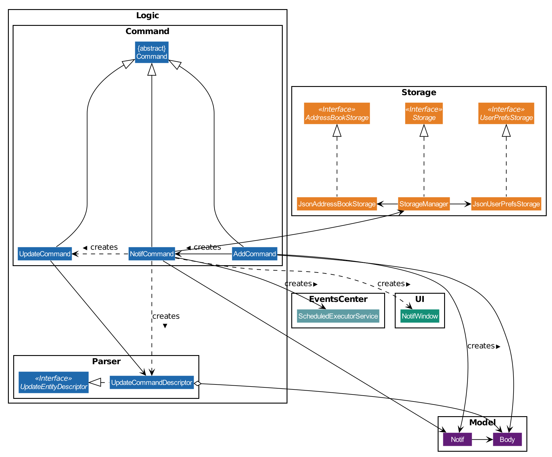
The following class diagram (Figure 15) models the relationships and dependencies among classes in this feature:
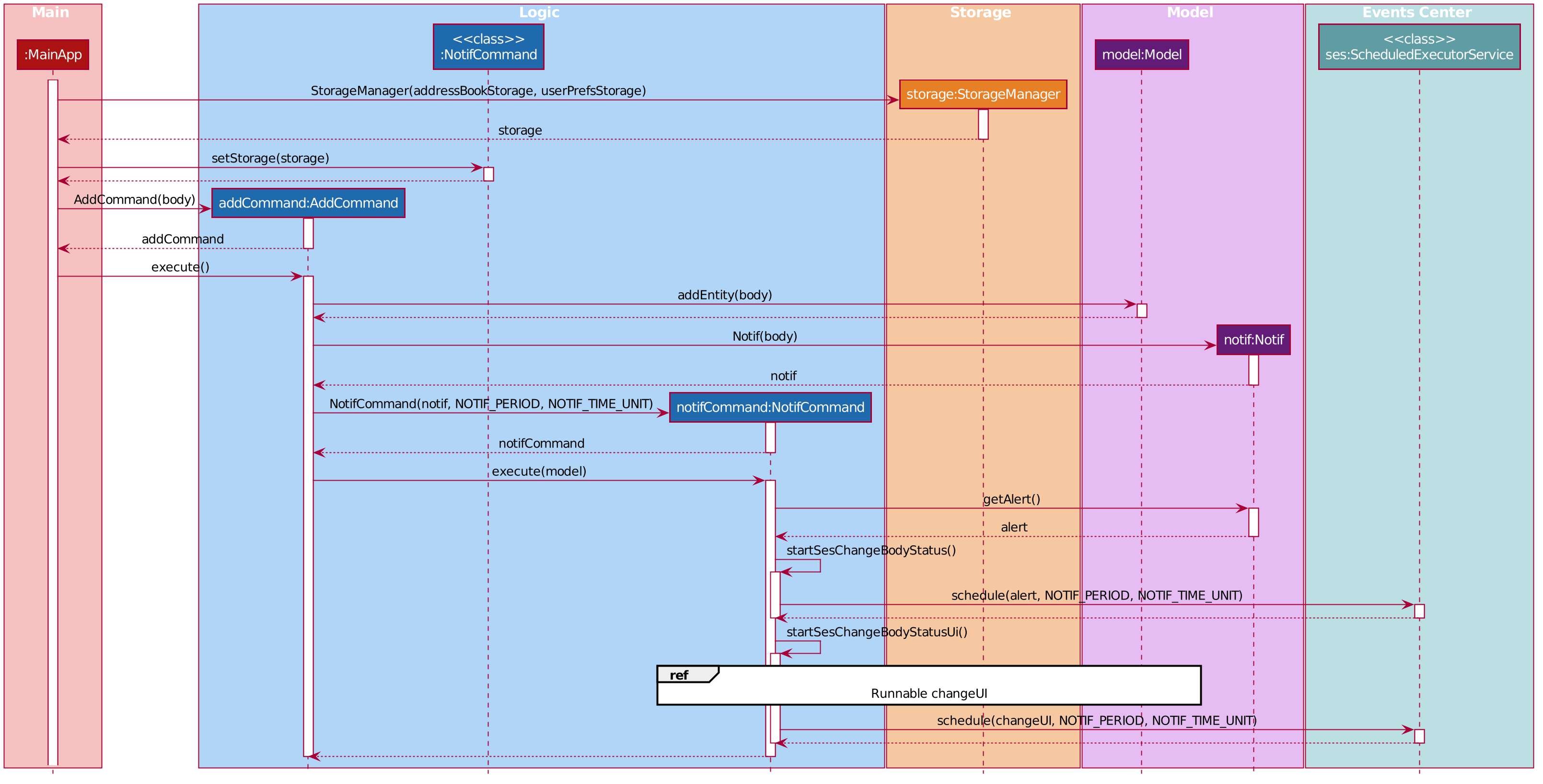
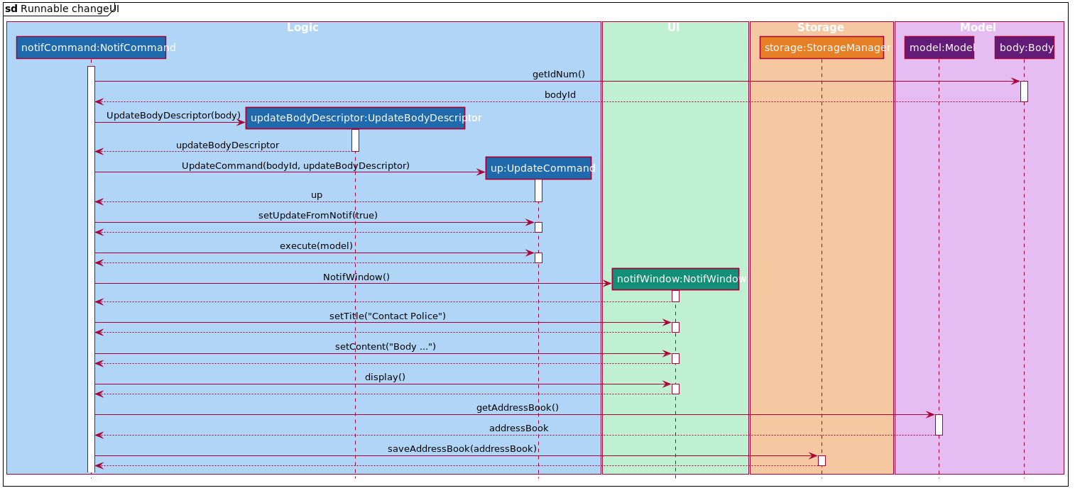
The following sequence diagrams (Figure 16 and 17) illustrate the execution of the notification feature:
The following activity diagram summarizes what happens when a user adds a new body and a NotifCommand is
instantiated:
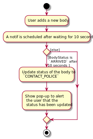
|
||
No! If the status of the |
Storing executed and pending Notifs
NotifCommand supports storage where each Notif with its associated Body and the long equivalent of the
notifCreationTime is stored in a JSON file along with the other Entities. When the MainApp is initialized, the
following happens:
-
All the
Notif(s) are fetched from the storage. -
For each
Notif, the difference of the current system time andnotifCreationTimeis calculated. -
If the difference is more than the
period, then the status of the associatedBodyis changed toCONTACT_POLICE. Otherwise, theNotifCommandis scheduled to be executed after the calculated time difference. -
The
Notifis added to the model.
|
||
|
Defensive programming
The NotifCommand heavily makes use of the ScheduledExecutorService and Platform.runLater(Runnable runnable) to
make changes to the Body status and Notif. They use threading to allow tasks to be handled concurrently. For instance,
even after scheduling a Runnable function, the user is still able to carry on with other commands of Mortago such
as updating the status of the Body, adding a new Fridge etc.
As per the official Java Documentation, Platform.runLater(Runnable runnable) runs the specified runnable function
on a thread dedicated to JavaFX application at some unspecified time in the future. So,
if some updates to the model are wrapped inside it as a Runnable while others are not, it can result in a
mismatch of model. For instance, you may want to delete a Notif which already exists in the model. The usual
process will be to first check whether it exists and if it does, then proceed with deletion. However, due to
threading, you may end up in a situation when the app finds the Notif at the point of checking but throws a
NullPointerException when proceeding with the deletion.
To prevent this, in Mortago, any addition or deletion of Notif in the model during the execution of the
NotifCommand and parts of UpdateCommand are wrapped inside Platform.runLater(Runnable runnable). This ensures
that updates to the model happen sequentially and not concurrently and the relevant changes can be reflected on the
UI.
Moreover, all these operations are wrapped inside a try-catch block. Either the NullPointerException or
DuplicateNotifException is directly thrown in the form of CommandException or it is logged in Logger. A
code snippet of NotifCommand to illustrate this is show below.
 if (model.hasNotif(notif)) {
    try {
        model.deleteNotif(notif);
    } catch (NullPointerException exp) {
        logger.info(MESSSAGE_NOTIF_DOES_NOT_EXIST);
    }
}

Platform.runLater(() -> {
    if (!model.hasNotif(notif)) {
        try {
            model.addNotif(notif);
        } catch (DuplicateNotifException exp) {
            logger.info(MESSAGE_DUPLICATE_NOTIF);
        }
    }
});
4.4.2. Design Considerations
Aspect: How to delay change in status of the Body
-
Alternative 1 (current choice): Use
ScheduledExecutorService.-
Pros: Does not depend on thread synchronization and avoids the need to deal with threads directly.
-
Cons: May cause memory leaks if cache is not cleared.
-
-
Alternative 2: Use
Thread.sleep-
Pros: Straightforward way to delay a thread.
-
Cons: May quickly run into OutOfMemory error.
-
Alternative 1 is the current choice because of its simplicity and robustness as it abstracts away the need to manually deal with threads.
Aspect: How the behaviour of NotifCommand differs when the app is initialized
-
Alternative 1 (current choice): Do not show a pop-up if the difference between system time and
notifCreationTimeexceedsperiod.-
Pros: Prevents the situation of multiple pop-ups on app initialization.
-
Cons: Does not prompt the user who may in turn forget to contact the police.
-
-
Alternative 2: Show pop-up on app initialization for
Notif(s) in storage for which the difference between system time andnotifCreationTimeexceedsperiod.-
Pros: Ensures that the user does not forget about contacting the police.
-
Cons: May slow down the computer and lag the app if there are too many pop-up notifications at the same time.
-
Alternative 1 is the current choice because we want the app to be responsive and scalable in the long term. The notification bell is placed beside the command box to prevent instances of user forgetting to contact the police.
4.5. Generate PDF Feature
This feature allows manager to automatically generate different kinds of reports with three commands: genReport, genReports and genReportSummary.
4.5.1. Implementation
The generate PDF feature is facilitated by ReportGenerator class.
It extends Mortago with the ability to create a report, supported by iText external library.
Additionally, it implements the following operations:
-
ReportGenerator#generate(body, sign)— Creates report containing sign name of manager in a PDF file for the specific body. -
ReportGenerator#generateAll(sign)— Creates reports containing sign name of manager in a PDF file for all bodies registered in Mortago. -
ReportGenerator#generateSummary(sign)— Creates a tabular summary report containing sign name of manager in a PDF file for all bodies registered in Mortago.
The following sequence diagram (Figure 19) shows how the generate operation works:
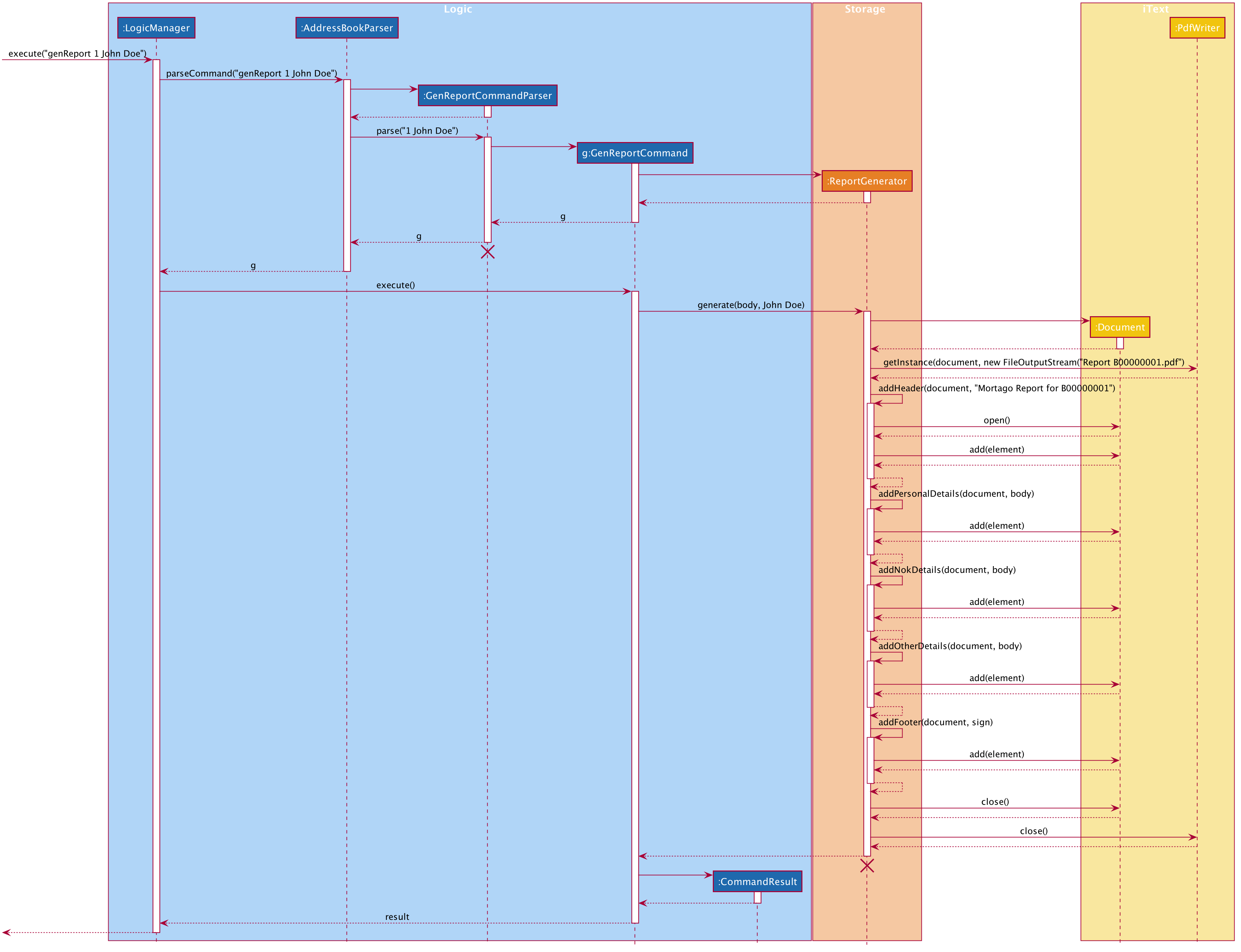
genReport 1 John Doe is executed by manager.
The lifeline for GenReportCommandParser and ReportGenerator should end at the destroy marker (X) but due to a limitation of PlantUML, the lifeline reaches the end of diagram.
|
The genReport <BODY_ID> (sign) command calls ReportGenerator#generate(body, sign), which creates the document.
The following activity diagram (Figure 20) summarizes what happens when manager executes a genReport <BODY_ID> (sign) command:
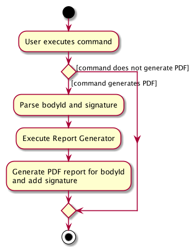
genReport 1 John Doe is executed by manager.The following code snippet from GenReportCommand.java demonstrates how an error message is displayed when manager inputs an invalid command and when report is not successfully generated:
if (bodyToGenReport == null) {
    throw new CommandException(MESSAGE_INVALID_ENTITY_DISPLAYED_INDEX);
}
boolean generated = reportGenerator.generate(bodyToGenReport, sign);
if (!generated) {
    throw new CommandException(MESSAGE_REPORT_NOT_GENERATED);
}
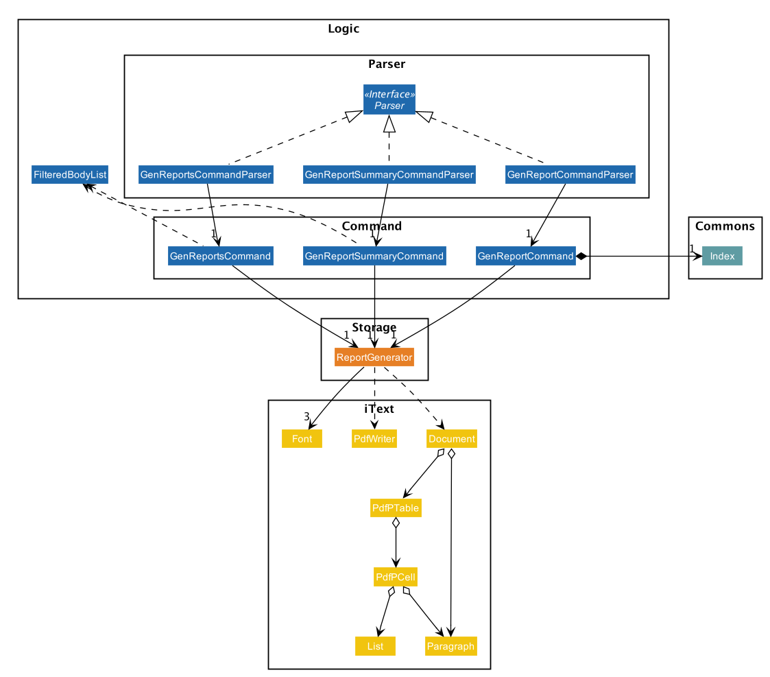
The following class diagram (Figure 21) models the relationships and dependencies among classes in this feature:
4.5.2. Design Considerations
Aspect: How generate report executes
-
Alternative 1 (current choice): Create a PDF file.
-
Pros: Implementation is easy.
-
Cons: Implementation must ensure that each individual body attribute is correct.
-
-
Alternative 2: Create a Word Document file.
-
Pros: Implementation allows manager to edit the contents of the report.
-
Cons: Implementation defeats the purpose of being automated.
-
Alternative 1 is the current choice because this will prevent manager from making accidental changes to the report when report is formatted in PDF.
Aspect: What library to utilise for generating PDF in Java
-
Alternative 1 (current choice): Use iText to implement this feature.
-
Pros: Implementation is simple because using iText would allow an API-driven approach.
-
Cons: Implementation is unable to use the latest version (iText 7) because it is not compatible, only version 5.5.13 is compatible.
-
-
Alternative 2: Use Apache PDFBox to implement this feature.
-
Pros: Implementation is easy because PDFBox is widely used and help is more accessible.
-
Cons: Implementation is limited because PDFBox can only create simple PDFs based on text files, supports few of the features iText does.
-
Alternative 1 is the current choice because this implementation does not require the enhancements provided by iText 7 but still requires more advanced library to create tables in a PDF document.
Aspect: How report is formatted
-
Alternative 1 (current choice): Use tables to organise related details in the report.
-
Pros: Implementation allows report to be organised, increases readability for manager.
-
Cons: Implementation is tedious.
-
-
Alternative 2: List all attributes in the report without any formatting.
-
Pros: Implementation is easy.
-
Cons: Implementation decreases readability for manager.
-
Alternative 1 is the current choice because manager will be able to save time and reduce work-related stress when manager is able to view an organised report.
4.6. Statistics Feature
4.6.1. Implementation
The statistics feature appears as a line chart of the number of bodies admitted over the past 10 days (default view) and is facilitated by LineChartPanel. It extends UiPart with an internal storage of the number of bodies admitted per day over the past 10 days. The line chart is part of the user interface and is initialised automatically when Mortago is launched. Users can switch the view to a specified week, month, or view.
In LineChartPanel, four key operations that constructs the line chart and updates it dynamically are implemented, and they are executed in order as described below:
-
LineChartPanel#initialiseTreeMap()— Initialises a tree map that contains the dates as the keys and the number of bodies admitted as the frequency. -
LineChartPanel#initialiseLineChart()— Creates a Line Chart with Xaxis and Yaxis. -
LineChartPanel#updateSeries()— Adds data to the series of the line chart based on what is in the tree map. -
LineChartPanel#updateUponChanged()— If a body is added or removed, the tree map is changed accordingly depending on the date of admission of the body, and the series is updated again.
The above operations are invoked through a wrapper function LineChartPanel#makeLineChart() which is invoked when the user calls LineChartPanel#getLineChart().
The line chart is updated automatically because it takes in an ObservableList<Body> from the AddressBook, so it re-intialises once a change has been detected. The following sequence diagram shows hows adding a body changes the AddressBook, and then how`LineChartPanel` interacts AddressBook to obtain an observable list of bodies, creates a line chart from it, and then passes the line chart to be displayed in MainWindow with dynamic update:
)Sequence diagram showing the dynamic update of the line chart when user adds a new body. image::LineChartAddBodySequenceDiagram.png[]
The user is able to switch the time frame of the line chart between the last ten days or a particular week, month, or year with the stats command (See User Guide). The following sequence diagram shows how the stats command affect the appearance of the line chart:
)Sequence diagram showing the changing view of the line chart when user specifies a different time frame. image::LineChartTimeFrameSequenceDiagram.png[]
4.6.2. Design Considerations
Aspect: How data is stored and updated
The line chart needs data to refer to. Below are two alternatives for how to access the data and update the line chart:
-
Alternative 1 (current choice): Data is not stored. Use a tree map to keep track of bodies and initialise the treemap depending on the given time frame.
The following activity diagram illustrates the current choice for accessing and updating data:
)Activity diagram for how the line chart populate values over the last ten days. image::LineChartActivityDiagram.png[]
-
Pros: Implementation is easy.
-
Cons: Series is regenerated whenever there is a change in time frame. As can be seen from the activity diagram below, the series gets reintialised regardless of whether it will affect a change in the appearance of the line chart.
-
Alternative 2: Store all data in a separate storage class.
-
-
Pros: No need to reinitialise the treemap everytime a
statscommand is called. -
Cons: Implementation requires a lot of storage which may not be tapped on most of the time.
Aspect: The time frame of the line chart
Currently the line chart supports four types of time frames as aforementioned. Below are two alternatives to which users are limited by the time frames:
-
Alternative 1 (current choice): Users can toggle between four types of time frames.
-
Pros: Implementation is easy and simple.
-
Cons: The statistics is limited in meaning if it cannot be compared between other time frames.
-
-
Alternative 2: Users can print a summary of statistics over a specified period.
-
Pros: The statistics will have more meaning.
-
Cons: Implementation is difficult.
-
4.7. User Interface and Dashboard Enhancement
The dashboard of Mortago plays a key part in presenting a sleek, organised, and concise overview to the entities in the system. Thus, designing an aesthetic and functional dashboard is a crucial aspect for Mortago.
4.7.1. Surface Design and Coloring
This section illustrates the motivations made behind Mortago’s color scheme.
4.6.1.1. Implementation
Mortago draws upon the guidelines specified in Material.io to design a dark theme that enhances visual ergonomics and minimises eye strain due to the bright luminance emitted by screens.
Designing the Visual Contrast Between Surfaces and Text
With reference to Web Content Accessibility Guidelines’ (WCAG), the guidelines recommend that the contrast level between dark surfaces and white text to be at least 15:8:1 to ensure visual accessibility. Thus, the following color values that complies with the above standards are chosen:
| Aspect of Mortago | Color | Color Preview |
|---|---|---|
Background |
derive(#121212, 25%) |

|
Surface |
#121212 |

|
Primary |
#FF7597 |

|
The background color uses the derive function in JavaFX, which computes a color that is brighter or darker than the original,
based on the brightness offset supplied.
The primary color is also desaturated to reach a WCAG’s AA standard of minimally 4:5:1.
This facilitates a mild yet impressionable visual aspect to Mortago while minimizing eye strain, as saturated colors can cause optical vibrations against the dark surface and exacerbate eye strain.
4.6.1.2. Design Considerations
This section details an aspect considered when designing Mortago’s color scheme.
Aspect: The contrast in brightness between the background and surfaces
-
Alternative 1 (current choice): Background is brighter than the surface.
-
Pros: Drop shadows designed to simulate elevation are more realistic
-
Cons: A deviation from what Material.io dictates
-
-
Alternative 2: Background is darker than the surface.
-
Pros: A different representation of elevation can be achieved
-
Cons: Overall visual brightness will be brighter compared to Alternative 1
-
Alternative 1 was chosen because, aside from the pros that it has to offer, bulk of the screen space in the Mortago is taken up by surfaces to optimize the amount of information available to the user, hence by giving surfaces a darker brightness, this improves overall visual ergonomics.
4.7.2. Replacing Window’s Title Bar
This section details how the default window’s title bar is replaced with a custom title bar.
4.6.2.1. Implementation
In spirit with designing a sleek and functional dashboard, the standard Windows platform title bar was removed. This exposes the user interface to become one that is self-contained, while providing extra space at the top that allows more details to be shown to the user.
How the window’s title bar was removed
The following code snippet demonstrates how the title bar was removed.
primaryStage.initStyle(StageStyle.TRANSPARENT);Note that this code was placed in MainApp#start() and has to be done before the stage is shown. Otherwise, the application will close automatically upon running.
However, with this removal, the default windows functions such as the default OS close button will inevitably be removed as well. Hence, these buttons will have to be rebuilt into the application.
How the default window functions were rebuilt
This section demonstrates how the default window function were rebuilt into the application.
Three buttons were manually created and customised to simulate the original window buttons. Each button was assigned to its respective handler method, based on different events. The following details the function of each button is recreated:
-
Exit Button
-
The method for exiting the application has already been implemented in
handleExit()in Address Book 3. Thus, setting the handler for the exit button to this method within theMainWindow.fxmlfile is sufficient.
-
-
Minimise Button
-
Minimisation of the application is implemented such that when the user clicks on the minimise button, it triggers an
onMouseClickedevent that callsprimaryStage.setIconified(true)which minimises the window. Hence, setting theonMouseClickedhandler to call this function is sufficient to implement minimisation through this button..
-
-
Maximise Button
-
Maximisation is implemented slightly different compared to minimisation. When the maximise button is clicked initially, the window should be maximised. When the button is clicked for the second time, the window should be restored to its pre-maximised size. Hence, notice that this button has two functions: maximisation and restoration. This switch in function is achieved via the following code snipped shown below.
/** * Enables the maximization and restoration of the window. */ private void maximiseRestore() { if (primaryStage.isMaximized()) { primaryStage.setMaximized(false); if (primaryStage.getScene().getWindow().getY() < 0) { primaryStage.getScene().getWindow().setY(0); } maximiseButton.setId("maximiseButton"); } else { Rectangle windowBounds = GraphicsEnvironment.getLocalGraphicsEnvironment().getMaximumWindowBounds(); primaryStage.setMaximized(true); primaryStage.setHeight(windowBounds.height); primaryStage.setWidth(windowBounds.width); maximiseButton.setId("restoreButton"); } } -
The
onMouseClickedhandler is set to call the above function such that when the button is clicked, if the window is maximised, the window will be restored to its original size, and if the window is not maximised, the window will be maximised. -
Notice also that the button is assigned to different
FXMLids for theifandelseblocks. This allows the button image to change accordingly, which is defined in theDarkTheme.cssstylesheet.
-
Finally, the last thing is to rebuild the resizability of the window.
The implementation of this feature is adapted from this hyperlinked post in StackOverFlow. Briefly, ResizableWindow::enableResizableWindow() allows the Windows to be resizable by implementing a helper class ResizeListener. The helper class listens to mouse events and tracks the mouse’s movements to pinpoint the coordinates of the mouse. This determines the change in size of the Window, which will then be resized accordingly.
4.6.2.2. Design Consideration
The following section details an aspect to consider when designing the title bar.
Aspect: Designing the default window’s title bar
-
Alternative 1 (current choice): Replace the default title bar with a custom title bar
-
Pros: Sleek interface that is pleasing to the eye and showcases a comprehensive product design
-
Cons: Default window functions have to be rebuilt into the application
-
-
Alternative 2: Retain the default title bar
-
Pros: Window functions will be perfectly working
-
Cons: The default title bar does not fit into the theme of the user interface
-
Alternative 1 was chosen despite the need to rebuild the default window functions as it is imperative to produce a complete product design. The visual appearance of the dashboard is a significant feature of the application as it details all the necessary information to the user. Hence, a product design that is visually appealing is necessary to attract more users and gain traction into opting our application.
4.8. Logging
We are using java.util.logging package for logging. The LogsCenter class is used to manage the logging levels and logging destinations.
-
The logging level can be controlled using the
logLevelsetting in the configuration file (See Section 4.9, “Configuration”) -
The
Loggerfor a class can be obtained usingLogsCenter.getLogger(Class)which will log messages according to the specified logging level -
Currently log messages are output through:
Consoleand to a.logfile.
Logging Levels
-
SEVERE: Critical problem detected which may possibly cause the termination of the application -
WARNING: Can continue, but with caution -
INFO: Information showing the noteworthy actions by the App -
FINE: Details that is not usually noteworthy but may be useful in debugging e.g. print the actual list instead of just its size
4.9. Configuration
Certain properties of the application can be controlled (e.g user prefs file location, logging level) through the configuration file (default: config.json).
4.10. [Proposed] Data Encryption
{Explain here how the data encryption feature will be implemented}
5. Documentation
Refer to the guide here.
6. Testing
Refer to the guide here.
7. Dev Ops
Refer to the guide here.
Appendix A: Product Scope
Target user profile:
-
has a need to manage a significant number of bodies
-
prefer desktop apps over other types
-
can type fast
-
prefers typing over mouse input
-
is reasonably comfortable using CLI apps
Value proposition: Mortago replaces and improves upon the traditional whiteboard system. It provides a convenient dashboard for the mortuary manager to keep track of all bodies and fridges, outstanding tasks, and notifications. Mortago unites the different aspects of a mortuary and allows the mortuary management to be more accurate in managing tasks, calculate the availability of space, and generates reports automatically.
Appendix B: User Stories
Priorities: High (must have) - * * *, Medium (nice to have) - * *, Low (unlikely to have) - *
| Priority | As a … | I want to … | So that I can… |
|---|---|---|---|
|
mortuary manager |
keep track of all bodies and fridges in a single dashboard using the dashboard command |
look out for any outstanding work and keep myself up to speed |
|
mortuary manager |
have a dynamically updated dashboard |
reduce errors as compared to manually updating a whiteboard |
|
mortuary manager |
key new bodies into the system |
keep track of them |
|
mortuary manager |
sort the bodies by certain characteristics |
view bodies of a speciic category and generate statistics easily |
|
mortuary manager |
filter the bodies by certain characteristics |
view bodies of a certain category and generate statistics easily |
|
mortuary manager |
update the status of each and every worker, body and fridge |
know when (date & time) was each step of the process completed and the findings of each process (eg. cause of death) |
|
mortuary manager |
delete a worker, body and fridge |
remove a worker when he quits, remove a wrong entry of the body, or remove a fridge |
|
mortuary manager |
switch between the dashboard and the detail views |
view information in an appropriate format |
|
mortuary manager |
view all free and vacant fridges |
keep track of the overall vacancy of the morgue |
|
mortuary manager |
view all registered bodies |
view all bodies in the morgue |
|
mortuary manager |
view all registered body parts |
view all body parts in the morgue |
|
mortuary manager |
view all the commands the app is capable of |
look at all the commands in one go |
|
mortuary manager |
view emergency hotlines |
be efficient and respond quickly to emergencies |
|
mortuary manager |
read up on the use of a specific command of the app |
understand a specific command which the app offers in more detail |
|
mortuary manager |
be alerted to bodies unclaimed after 24hours |
know when to start the administrative process of contacting the police |
|
mortuary manager |
receive routine reports from the app automatically |
need not manually write in each and every single report |
|
mortuary manager |
assign workers to tasks |
know who was responsible for a task |
|
mortuary manager |
can undo my previous tasks |
conveniently undo any wrong commands |
|
mortuary manager |
redo my previous tasks |
conveniently redo any undone commands |
|
mortuary manager |
add new or existing workers |
keep track of all the workers in the mortuary |
|
mortuary manager |
add new or existing fridge |
keep track of all the fridges in the mortuary |
|
mortuary manager |
be able to see a history of changes |
know if anything was inputted wrongly in the past |
|
mortuary manager |
create mortuary bills with the app automatically |
need not manually write in each and every single bill |
|
mortuary manager |
view bills for past reports and individual reports |
easily obtain past bills for my own reference / authorities / third party |
|
mortuary manager |
archive processed cases on a regular interval |
review past cases when such a need arises |
|
mortuary manager |
add comments and feedback to workplace processes |
review these feedback and improve on them |
|
mortuary manager |
feel happy when I see a beautifully designed dashboard |
keep my mood up throughout the day |
|
mortuary manager |
make sure that everything is organised and in order |
be praised by my higher ups |
Appendix C: Use Cases
(For all use cases below, the System is Mortago and the Actor is the mortuary manager, unless specified otherwise)
Use case: View dashboard
MSS
-
Mortuary manager requests to view the dashboard
-
Mortago displays the dashboard.
Use case ends.
Use case: Add body
MSS
-
Mortuary manager requests to add a body
-
Mortago adds the body into the system
Use case ends.
Extensions
-
1a. Duplicate body found.
-
1a1. Mortago shows an error message.
Use case restarts at step 1.
-
-
1b. Mandatory fields are missing.
-
1b1. Mortago shows an error message.
Use case resumes at step 1.
-
Use case: Delete body
MSS
-
Mortuary manager requests to list bodies.
-
Mortago shows a list of bodies.
-
Mortuary manager requests to delete a specific body in the list.
-
Mortago deletes the body from the system.
Use case ends.
Extensions
-
2a. The list is empty.
Use case ends.
-
3a. The given index is invalid.
-
3a1. Mortago shows an error message.
Use case resumes at step 2.
-
Use case: Find entry
MSS
-
Mortuary manager switches to the desired view (bodies or workers).
-
Mortuary manager specifies word to search.
-
Mortago shows a list of entries whose names matches the word.
Use case ends.
Extensions
-
3a. The list is empty.
Use case ends.
Use case: Filter entries
MSS
-
Mortuary manager switches to the desired view (bodies or workers).
-
Mortuary manager specifies criteria for filter.
-
Mortago shows a list of entries that matches the criteria.
Use case ends.
Extensions
-
3a. The list is empty.
Use case ends.
Use case: Sort entries
MSS
-
Mortuary manager switches to the desired view (bodies or workers).
-
Mortuary manager specifies criteria for sorting.
-
Mortago shows a list of entries sorted according to the specified criteria.
Use case ends.
Extensions
-
3a. The list is empty.
Use case ends.
Use case: Generate report
MSS
-
Mortuary manager requests to generate report for a specific body.
-
Mortago creates a new PDF report with body ID as the title.
Use case ends.
Extensions
-
1a. The given body ID is invalid.
-
1a1. Mortago shows an error message.
Use case ends.
-
Use case: Notification for unclaimed bodies.
MSS
-
Mortuary manager wants to be reminded of the next line of action if next of kin cannot be contacted within 24 hours.
-
Mortago maintains a record of all the notifications about bodies until their status is changed.
-
Mortago shows pop-up notification after 24 hours from the point of admission of the body in the mortuary.
Use case ends.
Extensions
-
1a. There are no notifications
Use case ends.
Use case: Undoing a previous command
MSS
-
Mortuary manager requests to undo the previous command.
-
Mortago undoes the command.
-
Mortago updates the GUI to reflect the new changes.
Use case ends.
Extensions
-
2a. There is no command to undo.
Use case ends.
-
2b. An error occurred when undoing the command.
-
2b1. Mortago shows an error message and nothing is changed.
Use case ends.
-
Use case: Redoing an undone command
MSS
-
Mortuary manager requests to redo the last undone command.
-
Mortago redoes the command.
-
Mortago updates the GUI to reflect the new changes.
Use case ends.
Extensions
-
2a. There is no command to redo.
Use case ends.
-
2b. An error occurred when undoing the command.
-
2b1. Mortago shows an error message and nothing is changed.
Use case ends.
-
Appendix D: Non Functional Requirements
-
Should work on any mainstream OS as long as it has Java
11or above installed. -
Should be able to hold up to 1000 bodies without a noticeable sluggishness in performance for typical usage.
-
A mortuary manager with above average typing speed for regular English text (i.e. not code, not system admin commands) should be able to accomplish most of the tasks faster using commands than using the mouse.
Appendix E: Glossary
- Mainstream OS
-
Windows, Linux, Unix, OS-X
- Body
-
A corpse
- Worker
-
An employee in the mortuary
- Fridge
-
A fridge used to store a body in the mortuary
- Notif
-
A notification to remind the mortuary manager of the bodies for which police needs to be contacted.
- Command-Line-Interface (CLI)
-
A text-based user interface (UI) used to view and manage computer files
- Graphical User Interface (GUI)
-
An interface through which a user interacts with electronic devices such as computers, hand-held devices and other appliances. This interface uses icons, menus and other visual indicator (graphics) representations to display information and related user controls, unlike text-based interfaces, where data and commands are in text
- System-Time
-
A computer’s current time and date
Appendix F: Instructions for Manual Testing
Given below are instructions to test the app manually.
| These instructions only provide a starting point for testers to work on; testers are expected to do more exploratory testing. |
F.1. Launch and Shutdown
-
Initial launch
-
Download the jar file and copy into an empty folder
-
Double-click the jar file
Expected: Shows the GUI with a set of sample contacts. The window size may not be optimum.
-
-
Saving window preferences
-
Resize the window to an optimum size. Move the window to a different location. Close the window.
-
Re-launch the app by double-clicking the jar file.
Expected: The most recent window size and location is retained.
-
F.2. Adding an Entity
-
Adding a new Body
-
Test case:
add -b /name John Doe /sex male /dod 11/11/2019 /doa 11/11/2019
Expected: The body is added and displayed on the dashboard.
-
-
Adding a new Fridge
-
Test case:
add -f
Expected: The fridge is added and displayed on the dashboard.
-
-
Adding a new Worker
-
Test case:
add -w /name Jahn Daah /sex male /dateJoined 11/11/2019
Expected: The worker is added and displayed on the dashboard.
-
F.3. Updating a Body
-
Updating a body while all bodies are listed
-
Prerequisites: List all bodies using the
list -bcommand. There is at least one body in the list. -
Test case:
update -b /id 1 /name Polly
Expected: The name of the body with ID 1 changes to Polly.
-
F.4. Deleting a Body
-
Deleting a body while all bodies are listed
-
Prerequisites: List all bodies using the
list -bcommand. Multiple bodies in the list. -
Test case:
delete -b 1
Expected: Body with body ID number 1 is deleted from the list. Details of the deleted body shown in the status message. Timestamp in the status bar is updated. -
Test case:
delete -b 0
Expected: No body is deleted. Error details shown in the status message. Status bar remains the same. -
Other incorrect delete commands to try:
delete -b,delete -b x(where x is larger than the list size)
Expected: Similar to previous.
-
F.5. Generating a Report
-
Generating a report for a specific body while all bodies are listed
-
Prerequisites: List all bodies using the
list -bcommand. At least one body in the list. Ensure all existing PDF reports are closed. -
Test case:
genReport 1 John Doe
Expected: Generate report success message shown in the status message. Report for body ID number 1 is generated in the folder containing the jar file. Details of the body shown in the report. Signature of John Doe shown in the report. -
Test case:
genReport 1
Expected: Generate report success message shown in the status message. Report for body ID number 1 is generated in the folder containing the jar file. Details of the body shown in the report. No signature shown in the report. -
Test case:
genReport 0
Expected: No report is generated. Error details shown in the status message. Status bar remains the same. -
Other incorrect generate report commands to try:
genReport,genReport x(where x is larger than the list size)
Expected: Similar to previous.
-
F.6. Using the Line Chart and Stats Command
-
Changing the time frame of the line’s chart horizontal axis
-
Prerequisites: None. The line chart is automatically displayed, with the last ten days as the default time frame.
-
Test case 1:
stats /week 25/10/2019
Expected: The line chart will show the seven days of the week that contains the day 25/10/2019. 25/20/2019 is a Friday but the line chart will show from Monday to Sunday. The label of the horizontal axis will change to "Day". -
Test case 2:
stats /month 10/2019
Expected: The line chart will show the 31 days of month of October, 2019. All dates will be shown on the horizontal axis but will be in a shortened format. The label of the horizontal axis will change to "October 2019". -
Test case 3:
stats /month 2/2019
Expected: The line chart will show the 28 days of month of February, 2019. All dates will be shown on the horizontal axis but will be in a shortened format. The label of the horizontal axis will change to "February 2019". -
Test case 4:
stats /year 2019
Expected: The line chart will show the 365 days of year 2019. Dates are in a shortened format but not all dates will be shown on the horizontal axis due to space constraint. The label of the horizontal axis will change to be "Year 2019". -
Test case 5:
stats /year 2016
Expected: The line chart will show the 366 days of leap year 2016. Not all dates will be shown on the horizontal axis due to space constraint. The label of the horizontal axis will change to be "Year 2016". -
Test case 6:
stats
Expected: The line chart will show the last ten days from the current date. The label of the horizontal axis will change to be "Day". -
Incorrect stats commands to try:
stats 9/2019,stats 2019,stats /week 40/23/2019,stats /month 40/2009Expected: An error message will appear informing you that the command format is invalid or the date entered is invalid.
-
-
Testing the dynamism of the line chart by adding and deleting bodies
-
Prerequisites: The time frame of the line chart should be changed to include the date of admission of the body that is going to be added.
-
Test case 1:
add -b /name Jonathan Bergeson /sex male /dod 14/11/2019 /doa 14/11/2019
Expected: The y-value for the date 14/11/2019 automatically decreases by 1. -
Test case 2:
delete -b <ID number of the previously added body>
Expected: The y-value for the date 14/11/2019 automatically decreases by 1.
-
F.7. Filter entries by attributes
-
Filter bodies by a combination of at least on attribute.
-
Prerequisites: List all bodies for better viewing of the entries.
-
Test case 1:
filter -b /sex female
Expected: Mortago will list only bodies that are female. The command result will specify how many bodies fit the criteria (0 if none). -
Test case 2:
filter -b /sex male /status pending police report
Expected: Mortago will list only bodies that are female and needs a police report written for it. The command result will specify how many bodies fit the criteria (0 if none). -
Test case 3:
filter -b /sex male /organsForDonation kidney liver /status arrived
Expected: Mortago will list only bodies that are male, donating kidney and liver, and has the status arrived. The command result will specify how many bodies fit the criteria (0 if none). -
Test case 4:
filter -b /status hello world
Expected: Mortago will not list any body and the command result will read "0 bodies listed!" as that status does not exist. -
Test case 5:
filter /sex male /cod car accident
Expected: An invalid command error will be thrown and the command result will display it as no flag was given. -
Incorrect filter commands to try:
filter,filter -b,filter -aExpected: An error message will appear informing you that the command format is invalid.
-
-
Filter workers by a combination of at least on attribute.
-
Prerequisites: List all workers for better viewing of the entries.
-
Test case 1:
filter -b /sex female
Expected: Mortago will list only female workers. The command result will specify how many bodies fit the criteria (0 if none). -
Test case 2:
filter -w /sex male /designation coroner
Expected: Mortago will list only male coroners. The command result will specify how many bodies fit the criteria (0 if none). -
Test case 3:
filter -w /employmentStatus hello world
Expected: Mortago will not list any body and the command result will read "0 bodies listed!" as that status does not exist. -
Test case 4:
filter /sex male /employmentStatus full-time
Expected: An invalid command error will be thrown and the command result will display it as no flag was given. -
Incorrect filter commands to try:
filter,filter -b,filter -aExpected: An error message will appear informing you that the command format is invalid.
-
F.8. Undoing/redoing a command
-
Undoing an
AddCommand-
Prerequisites: An entity was added to Mortago in the previous executed command.
-
Test case:
undo
Expected: The added entity is removed from Mortago.
-
-
Undoing an
UpdateCommand-
Prerequisites: A body or worker in Mortago was updated in the previous executed command.
-
Test case:
undo
Expected: The fields of the body or worker that was updated has gone back to its original state.
-
-
Undoing a
DeleteCommand-
Prerequisites: An entity in Mortago was deleted in the previous executed command.
-
Test case:
undo
Expected: The entity deleted reappears in Mortago.
-
-
Undoing a
ClearCommand-
Prerequisites: A
ClearCommandwas executed in the previous executed command. -
Test case:
undo
Expected: All entities existing in Mortago before theClearCommandwas executed reappears on the dashboard.
-
-
Redoing these commands
-
Prerequisites: You have just finished executing one of the above
undotest cases. -
Test case:
redo
Expected: Mortago’s state goes back to theundotest case’s prerequisite.
-
F.9. Saving Data
-
Saving your changes
-
Add a body to Mortago using this command:
add -b /name Agavoides Echeveria /sex male /dod 12/12/2018 /doa 22/10/2019 -
Notice that the body has appeared on the dashboard.
-
Close Mortago and reopen it to verify that the change was saved.
-
-
Dealing with missing or corrupted data files
-
Go to the folder that Mortago is stored in.
-
Delete every file except Mortago’s .jar file.
-
Run the jar file again to start a new, empty data file.
-
-
Simulating a corrupted data file
-
Go to the folder that Mortago is stored in and locate the data folder. addressbook.json will be found in the data folder.
-
Add an 's' to 'bodies' in line 3 of the file.
-
Run Mortago again. It will start Mortago with a new, empty data file.
-